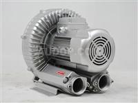
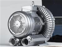
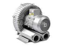
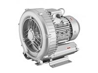
High-Pressure Blower

- It has dual functions of blowing and suction, one machine for two purposes, which can be used for suction or blowing; A certain type of high-pressure blower can also use suction and blowing at the same time, with a function similar to that of a rotary vane vacuum pump.
- It operates with little or no oil, and the output air is clean.
- Compared with centrifugal fans and medium-pressure fans, its pressure is much higher, often more than ten times that of centrifugal fans, with a maximum pressure of up to 230KPA.
- If the pump body is integrally die-cast and shockproof mounting feet are used, its requirements for the installation foundation are very low. It can even operate normally without fixing the feet, which is very convenient and can greatly save installation costs and installation cycle.
- Compared with other types of fans, its operating noise is lower, and the larger the power, the more obvious this advantage is, which can be shown when the power is above 5.5KW.
- Maintenance-free use; Its only wearing parts are two bearings, and basically no maintenance is required within the warranty period.
- The mechanical wear of the high-pressure blower is very slight. Except for the bearings, there are no other mechanical contact parts. Therefore, its service life is certainly very long. As long as it is under normal use conditions, a service life of 3 to 5 years is completely achievable. This is also the biggest reason for the popularization of domestic high-pressure fans.
Overview
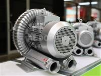
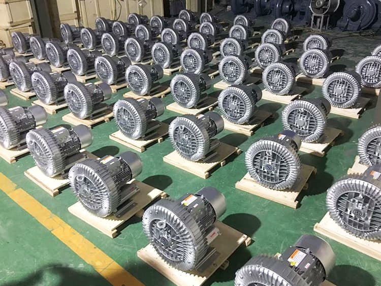
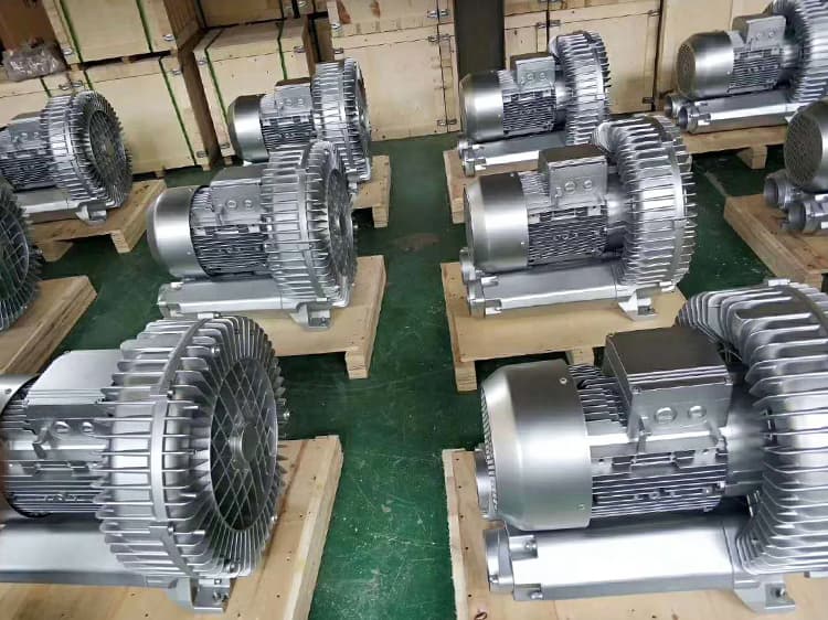
High-pressure blowers, also known as high-pressure fans or vortex fans, are different from ordinary centrifugal high-pressure blowers.Under design conditions, fans with an air pressure of 30kPa~200KPa or a compression ratio e=1.3~3 fall into the category of high-pressure blowers. Currently, in the industry, ring vacuum pumps are generally classified as high-pressure blowers.High-pressure blowers are mainly composed of motors, pump bodies, pump covers, gaskets, impellers, shaft sleeves, bearings, sealing rings and other components.Its applications cover industries such as medical care, pharmaceuticals, food, infrastructure construction, automotive industry, plastic industry, chemical industry, electrical and electronic industry, light industry and textile, shipping and railway, aerospace engineering, etc. With a wide application range, it meets the needs of equipment cleaning, material drying treatment and other requirements in various industries.
The impeller of a high-pressure blower is composed of dozens of blades, which is similar to the impeller of a large gas turbine.The air in the middle of the impeller blades is affected by centrifugal force and moves to the edge of the impeller. There, the air enters the annular cavity of the pump body and circulates again from the starting point of the blades in the same way.The circulating air flow generated by the rotation of the impeller leaves the air pump with extremely high energy for use.The high-pressure blower adopts a dedicated motor, featuring a compact structure, small size, light weight, low noise, and the delivered air source is free of water and oil.
Working Principle of High-Pressure Blower:
When the impeller rotates, due to the effect of centrifugal force, the wind deflector promotes the gas to move forward and outward, thereby forming a series of spiral movements.The air between the impeller blades rotates in a spiral and accelerates, squeezing the gas outside the pump body into the side groove (sucked in through the suction port). After entering the side channel, the gas is compressed and then returns to the space between the impeller blades to accelerate rotation again.When the air passes through the impeller and the side groove along a spiral path, each impeller blade increases the degree of compression and acceleration. As the rotation proceeds, the kinetic energy of the gas increases, which further increases the pressure of the gas passing through the side channel.When the air reaches the connection point between the side groove and the discharge flange (the side channel narrows at the outlet), the gas is squeezed out of the blades and discharged from the pump body through the outlet muffler.
Classification of High-Pressure Fan:
- Electric Type: The electric type uses a motor as power and is further subdivided into mechanical type and hydraulic type.
- Mechanical Type: The motor drives the crankshaft to make the plunger reciprocate, directly increasing the pressure of the material.With continuous pressure supplied by multiple groups of plungers, it has high homogeneous pressure and large output. However, it requires a large amount of materials. At the same time, the motor driving the crankshaft requires a multi-stage reduction mechanism, resulting in average equipment efficiency and large volume. It is suitable for large-scale production.
- Hydraulic Type: The motor drives the oil pump to increase the pressure of the material through the hydraulic system.The hydraulic system can provide higher pressure, with high equipment efficiency, relatively small volume and less material consumption. It is suitable for both experiments and production.
- Manual Type: The pressure of the material is increased through a manual lever mechanism.Due to manual pressure increase, its production capacity is low, but it has the advantages of easy disassembly and assembly and portability. At the same time, it requires a small amount of materials, so it is very suitable for small-volume experiments and can fully meet the R&D needs of laboratories.
- Pneumatic Type: It converts the pressure of compressed gas into hydraulic pressure.This equipment requires the support of nitrogen cylinders or air compressors, with large gas consumption and generally low homogeneous pressure. However, since there is no independent pressure-increasing mechanism, it has a small volume and is suitable for use in places equipped with air compressors.
Composition Structure of High-Pressure Fan:
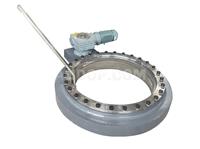
High-pressure blowers are composed of shafts, impellers, bearings, synchronous gears, couplings, shaft sleeves, etc.
- Impeller: It adopts an involute profile, with high volume utilization rate.
- Bearing: The end close to the coupling is used as the positioning end, and a 3000-type double-row radial spherical roller bearing is selected. The end close to the gear is used as the free end, and a 32000-type single-row radial short cylindrical roller bearing is selected to adapt to the axial displacement of the rotor during thermal expansion.
- Synchronous Gear: Composed of a gear ring and a hub, it is convenient to adjust the impeller gap.
- Transmission Method: Mainly direct connection with a coupling. If required by performance standards, a V-belt pulley speed change method can also be selected. The coupling adopts an elastic coupling, which can mitigate impacts and compensate for minor axial errors.
Application Scope and Environment of Vortex Fan:
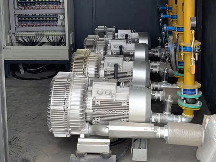
- Vacuum Suction Conveying and Vacuum Adsorption Applications: (Injection Molding Machine) Automatic Feeder, Automatic Conveyor, Central Feeding Machine, Vacuum Cleaner, Industrial Vacuum Cleaner; Injection Molding Machine, Vacuum Manipulator, Vacuum Crane, Vacuum Lifter, Leather Engraving Machine, Pad Printing Machine, Screen Printing Machine, Ventilation and Environmental Protection.
- Artificial Oxygenation: Oxygen supply at mine and tunnel construction sites, elimination of hazardous gas environments, oxygen supply in confined spaces, oxygen supply for fish ponds, oxygenation for aquaculture ponds.
- Air Agitation: Electroplating Agitation, PCB Chemical Reaction Tank Agitation, Other Chemical Reaction Tank Agitation, Water Treatment Aeration, Sanitary Ware, Swimming Pools, Hot Spring Equipment, Artificial Wave Engineering, Soil Purification Treatment.
Selection Notes for Vortex Fan:
Due to the wide application of high-pressure blowers, their selection is relatively complex. Generally, it needs to be carried out in the following two steps:
It is necessary to determine which function of the high-pressure blower is to be used on-site, whether it is suction or blowing, and find the corresponding pressure-flow curve of the high-pressure blower; Misreading the curve may sometimes result in the selected product being unusable.
Based on the calculated pressure and flow rate, find the working curve above the working point that meets both pressure and flow rate requirements on the curve graph; Then select the high-pressure blower model according to the working curve.
Installation Notes for High-Pressure Blowers:
- Flat washers and spring washers must be used to fasten the screws.
- It is better to use rubber buffer rubber to bear the weight of the high-pressure blower, which is essential especially for high-power high-pressure blowers.
- For occasions with noise requirements, a muffler can be installed to reduce noise (generally, by about 5dB). The muffler is installed at the end of the air inlet pipe or air outlet pipe.
- For occasions with high noise requirements, a layer of sound-absorbing cotton can be added according to the conditions of the machine itself to meet the on-site noise requirements. For details, you can consult high-pressure blower manufacturers or professional noise control companies.
- When using sound-absorbing cotton for noise reduction, pay attention to the distance between the high-pressure blower and the cabinet, the ventilation and heat dissipation of the high-pressure blower, and use rubber buffer rubber to bear the weight of the high-pressure blower. For details, you need to consult the high-pressure blower manufacturer.
- The air inlet and outlet pipes of the high-pressure blower should be connected with hoses to isolate vibration.
Maintenance of High-Pressure Blowers:
- Check the tightness of all parts and whether the positioning pins are loose. If loose, fasten them.
- Check whether there is oil leakage inside the blower body.
- There should be no scaling, rusting or peeling inside the blower body.
- Pay attention to whether the lubricating oil cooling is normal, the quality of the lubricating oil, often listen to whether there is abnormal noise during the operation of the blower, and pay attention to whether the unit is working under non-compliant operating conditions.
- The overload of the blower is sometimes not displayed immediately, so pay attention to the changes in inlet and exhaust pressure, bearing temperature and motor current to judge whether the machine is operating normally.
- When disassembling the machine, measure the matching dimensions of the machine, make records, and mark the parts with their positions and directions to ensure assembly and maintain the original matching requirements.
- For new machines or blowers after major maintenance, put them into operation according to the usage steps. It is recommended to replace all lubricating oil after 8 hours of operation.
- Under normal conditions, the unit is required to replace the lubricating oil after 1000 hours of operation. After-sales service for failure to change oil on time is not within the scope of free three guarantees.
- Daily maintenance is very important. Minor faults must be repaired before putting the machine into use again.
Technical Parameters
Technical Parameters
| Model | Number of impellers | Power(kw) | Maximum flow(m³/h) | Rated vacuum(mbar) | Rated discharge pressure(mbar) | level of noise (dBA) | Diameter (inches) |
| ADP 210-H16 | single | 0.4 | 80 | -120 | 130 | 53 | 1.2 |
| ADP 310-H06 | single | 0.55 | 100 | -110 | 120 | 55 | 1.2 |
| ADP 320-H36 | double | 1.3 | 110 | 280 | 290 | 58 | 1.2 |
| ADP 410-H16 | single | 0.85 | 145 | -160 | 160 | 63 | 1.5 |
| ADP 420-H46 | double | 2.2 | 150 | -320 | 420 | 66 | 1.5 |
| ADP 510-H26 | single | 1.6 | 210 | -200 | 190 | 64 | 2 |
| ADP 520-H46 | double | 3 | 230 | 340 | 410 | 72 | 2 |
| ADP 610-H16 | single | 2.2 | 265 | -235 | 220 | 69 | 2 |
| ADP 710-H26 | single | 3 | 318 | -260 | 270 | 72 | 2 |
| ADP 720-H47 | double | 5.5 | 320 | 420 | 500 | 76 | 2 |
| ADP 720-H57 | double | 7.5 | 320 | 420 | 610 | 76 | 2 |
| ADP 810-H17 | single | 5.5 | 530 | -300 | 300 | 70 | 2.5 |
| ADP 810-H27 | single | 7.5 | 530 | -320 | 430 | 70 | 2.5 |
| ADP 820-H37 | double | 11 | 520 | 430 | 600 | 74 | 2.5 |
| ADP 820-H47 | double | 15 | 520 | 460 | 670 | 74 | 2.5 |
| ADP 910-H07 | single | 8.5 | 1050 | -190 | 190 | 74 | 4 |
| ADP 910-H17 | single | 12.5 | 1050 | -290 | 280 | 74 | 4 |
| ADP 910-H37 | single | 18.5 | 1050 | -360 | 460 | 74 | 4 |
Your requirements are the basis for our development and a daily challenge to bring to fruition, please do not hesitate to inquiry us.

Scraper Arch Breaker
- High-Quality Material Guarantee: The main body is made of SUS304 stainless steel, which has stable physical properties. It is not only corrosion-resistant and wear-resistant but also meets the hygiene level requirements of the food and pharmaceutical industries, avoiding contamination when materials come into contact with the equipment. SUS304 stainless steel scraper arch breakers are safe for food-grade applications.
- Simple Structural Design: The overall structure has no complex redundant parts and adopts a "bolt-free" assembly process, reducing gaps for material accumulation and cleaning blind spots. During daily maintenance, there is no need to disassemble complex components; only the scraper wear condition and gear lubrication status need to be checked, which greatly reduces maintenance costs and downtime. Low-maintenance scraper arch breakers save production costs for factories.
- Long Service Life: The core transmission components (gears) adopt precision machining technology, and combined with the wear-resistant treatment of the scraper, mechanical loss during operation is reduced. At the same time, compared with chain transmission, the gear transmission method avoids the risk of chain loosening and breaking, and the average service life of the equipment is more than 30% longer than that of traditional discharging equipment. Long-life scraper arch breakers reduce equipment replacement frequency for manufacturers.
- Significant Arch-Breaking and Wall-Cleaning Effect: The design of the scraper making circular motion along the silo wall can directly act on the retained materials on the side walls and bottom of the silo. It not only solves the "bridging" and "hollowing" problems but also cleans the materials attached to the silo wall, avoiding caking and deterioration caused by long-term material retention and improving material utilization rate. Scraper arch breakers with excellent wall-cleaning function enhance production efficiency.
- Alleviating Material Segregation: For mixed materials with uneven particle sizes, traditional discharging methods are prone to "segregation" (large particles concentrate at the bottom and small particles concentrate at the top) due to different particle settlement speeds, which affects subsequent production quality. The scraper arch breaker keeps the materials in a mixed state during the falling process through the uniform stirring and pushing of the scraper, effectively alleviating the segregation problem. Scraper arch breakers prevent material segregation for consistent product quality.
- Quiet Operation Experience: The gear transmission link adopts a high-precision meshing design, and combined with the lubrication treatment of bearings, the noise during operation is controlled below 60 decibels (equivalent to the volume of daily conversation), avoiding the harsh noise of traditional discharging equipment during operation and improving the workshop working environment. Quiet scraper arch breakers create a comfortable working environment for production line engineers.
- Wide Hopper Angle Adaptability: It can adapt to hopper angles within 45°. Whether it is a vertical silo or an inclined silo, accurate connection can be achieved by adjusting the installation angle, without the need for large-scale modification of the existing silo structure. Scraper arch breakers with flexible hopper angle adaptation fit various silo types.
- Rich Specifications and Customization Options: Standard caliber specifications from φ40 to φ500 are provided, covering different needs from small laboratory equipment to large-scale industrial production lines. For large-caliber needs beyond the standard caliber (such as above φ500), exclusive equipment can be customized through technical consultation according to the customer's silo size and material characteristics, ensuring seamless connection with the existing production system. Customizable scraper arch breakers meet diverse industrial needs for purchasers.
- Expandable Blade Design: It supports the installation of multiple scraper blades (the specific number is determined according to material fluidity and discharging volume). The more blades there are, the higher the discharging efficiency and the more uniform the material stirring, which can be flexibly adjusted according to the actual production rhythm. Expandable blade scraper arch breakers optimize discharging efficiency for different production beats.
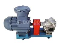
KCB Series Gear Pump
- KCB Series Gear Pump is mainly composed of gears, shafts, pump body, relief valve and shaft end seal. The gears undergo heat treatment to achieve high hardness and strength, and are installed in replaceable shaft sleeves together with the shafts for operation. The lubrication of all parts in the KCB Series Gear Pump is automatically achieved by using the output medium when the pump is working.
- The pump is designed with reasonable oil discharge and oil return grooves, which reduce the torque force borne by the gears during operation. As a result, the bearing load is small, wear is minimal, and the KCB gear oil pump has high efficiency.
- KCB Gear Pump is equipped with a relief valve for overload protection. The full return pressure of the relief valve is 1.5 times the rated discharge pressure of the pump. The KCB gear oil pump can also be adjusted separately according to actual needs within the allowable discharge pressure range. However, it should be noted that this relief valve cannot work as a pressure reducing valve for a long time; if necessary, a separate pressure reducing valve can be installed on the pipeline. When viewing the pump from the extended end of the main shaft, the rotation direction is clockwise.
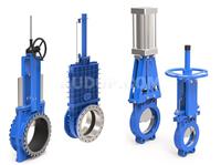
Knife Gate Valve
- Ultra-short structural length saves materials and greatly reduces the overall weight of the pipeline system matched with the knife gate valve.
- It occupies small effective space, effectively supports pipeline strength, and reduces the possibility of pipeline vibration when used with the knife gate valve.
- The gate plate of the knife gate valve is made of austenitic stainless steel, which greatly improves corrosion resistance and effectively prevents sealing leakage caused by gate plate corrosion.
- The upper sealing packing of the knife gate valve adopts flexible PTFE, ensuring reliable sealing and easy, flexible operation.
- The gate plate of the knife gate valve has a knife function, which can effectively cut off various impurities in the medium.
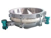
Bin Bottom Vibratory Discharger
- Low power consumption, high efficiency and obvious effect.
- The discharge hopper is integrally stamped, with good rigidity and smooth inner wall. The built-in tapered discharge plate protrudes upward to ensure no material residue in the discharger.
- The vibration force and amplitude can be easily adjusted.
- The fixing bolts of the discharge plate are assembled from top to bottom, which improves safety.
- Low noise generated by vibration, meeting environmental protection requirements.
- Safe and reliable to use, with safety protection devices.
- Simple and novel equipment structure, convenient installation and low maintenance rate.

Roots Blower
- It has the characteristic of forced transportation. Under the condition of a certain rotating speed, the flow rate is basically unchanged. Even in the small flow rate area, surge will not occur, and it has stable working characteristics.
- As a rotary machine, it has no reciprocating mechanism, no air valve, few wearing parts and a long service life.
- It inhales and exhausts air many times in one operation cycle. Compared with the piston compressor, the air flow speed is uniform and there is no air storage tank.
- There is a certain gap between the moving parts and the static parts, and no lubricating oil is needed in the chamber, which ensures that the transported gas is oil-free and no oil-gas separation device is required.
- There is no internal compression process, and the mechanical efficiency is high.