Pneumatic Conveying Pump


- High Energy Efficiency: Due to the reasonable fluidization structure, the material fluidization state is good, and the air consumption is significantly lower than that of similar products. After years of production and research, our company has improved the fluidization structure for many times, which greatly improves production efficiency and reduces energy consumption, helping users save operating costs.
- High Material-Gas Ratio: With good fluidization effect and low air consumption, the material-gas ratio is naturally high. Through laboratory tests, when the equivalent distance is within 500 meters, the material-gas ratio can reach more than 30Kg (ash)/Kg (gas), ensuring efficient material conveying.
- Low Material Flow Rate: The material flow rate during conveying is low, which results in small wear of the equipment's valves and pipelines and long service life of vulnerable parts, reducing the frequency of equipment maintenance and replacement.
- Strong Adjustment Function: It has various adjustment methods such as primary and secondary air intake adjustment, which can make the system operate under the optimal air consumption ratio and excellent fluidization state, adapting to different material conveying conditions.
- Unique Blockage Removal Method: It adopts a back-suction blockage removal method, which is simple, easy to implement and reasonable in operation. It only needs to lead the material-gas mixture to the silo or flue inlet through the blockage removal valve and pipeline, ensuring smooth operation of the conveying system.
- Easy Solution for Supporting Facilities: Due to low air consumption and low speed, the silo material-gas separation and filtration equipment can be smaller than that equipped with general bin-type pumps, and the air pollution caused is also small, meeting environmental protection requirements.
- Small Energy Consumption Coefficient: The energy consumption coefficient of the bin-type pump conveying system is below 65KW.h/t.m, which is more energy-saving compared with similar conveying systems.
- High Degree of Automation: It adopts a programmable (PLC) control system, and the entire working process can be fully automated. The system can be set to automatic or manual operation mode. The main control cabinet is installed in the system control room, reducing manual operation intensity and improving operation accuracy.
Overview
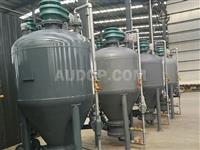
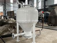
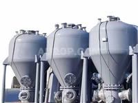
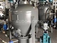
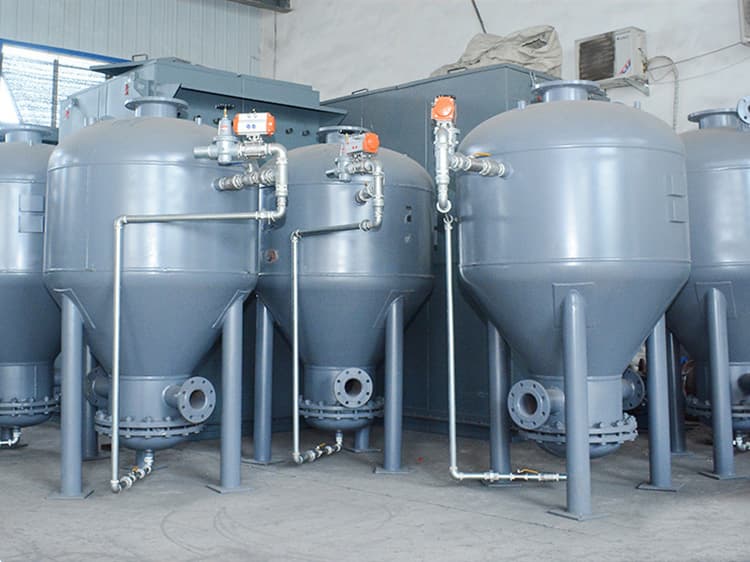
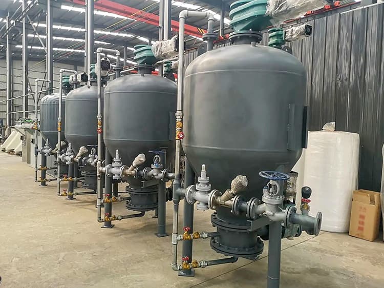
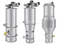
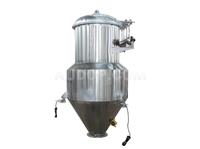
Bin-type pneumatic conveying pump is an industrial conveying equipment mainly used for the transportation of solid materials. It features material conveying, quantitative feeding, anti-clogging, dust reduction, space saving, low noise, easy maintenance and strong material adaptability, making it an ideal choice for industrial solid material handling.Its working principle covers feeding, conveying and discharging stages. As an important equipment in industrial production, the bin-type pneumatic conveying pump is widely used in various industries for efficient solid material transfer.
Composed of a diffusion chamber, pump body, movable air duct, actuator and other components, the bin-type pneumatic conveying pump is widely applied in the transportation of powder materials such as power plant fly ash, cement, cement raw meal and mineral powder.The conveying pipelines can be flexibly arranged according to topographic conditions to achieve centralized, decentralized, high-altitude and long-distance conveying. The conveying process is not affected by natural conditions, which can ensure that materials are not damp and realize environmental protection without pollution, meeting the environmental requirements of modern industrial production.This pneumatic conveying pump adopts a PLC control system, allowing automatic or manual control. With stable performance, reliable quality and dust-free conveying, it is an ideal pneumatic conveying equipment for industrial material handling needs.
Pneumatic conveying pump is a relatively reliable dense-phase dynamic pressure pneumatic conveying device for transporting powder materials under high pressure (below approximately 700kPa), suitable for various powder material conveying scenarios.It has two discharging methods, among which bottom discharging is the most commonly used one. The materials in the tank can be fluidized through inflation of the conical air inflation groove, nozzle air injection or other methods; setting a fluidized air inflation plate (layer) at the bottom enables the materials to be discharged from the upper part of the tank, enhancing the flexibility of material discharging.The distribution of conveying gas on different input planes in the tank depends on the properties of the conveyed materials, so it is necessary to select the appropriate configuration according to the actual material characteristics.
Applications of Pneumatic Conveying Pump:
Pneumatic conveying pump is suitable for conveying powder materials such as fly ash, cement, cement raw meal, carbon powder, mineral powder, grain and chemical raw materials, widely meeting the material conveying needs of power, building materials, chemical and food industries.
Working Process of Vacuum Pump for Pneumatic Conveying:
- Open the feeding valve and exhaust valve, and the conveying pump feeds under normal pressure until the horizontal level gauge sends a signal indicating that the bin is full, ensuring accurate material feeding volume.
- Close the feeding valve and exhaust valve, then open the high-pressure gas valve to pressurize the inside of the tank, creating a suitable pressure environment for material conveying.
- When the operating pressure is reached, open the conveying air valve and discharging valve, and the material starts to be conveyed stably.
- The end of conveying is indicated by a pressure switch, level gauge or time relay. At this time, close the high-pressure gas valve and discharging valve, so that all compressed air is used to purge the conveying pipeline; at the same time, open the exhaust valve to reduce the pressure inside the tank to normal pressure. After one working cycle is completed, another cycle continues, realizing continuous and efficient material conveying.
Structure of Vacuum Pump for Pneumatic Conveying:
- Feeding Device: Also called feeding valve, it is installed on the upper part of the pneumatic conveying pump and used to control the feeding of the pneumatic conveying pump. It uses an air cylinder to control the up and down movement of the conical valve, thereby opening and closing the feeding port, ensuring smooth material feeding.
- Exhaust Device: Also called exhaust valve, it is installed on the upper part of the pneumatic conveying pump. Its function is to open or close the valve through the action of the air cylinder, so that the residual air in the pneumatic conveying pump is discharged to the storage bin, maintaining the normal pressure inside the pump.
- Fluidization Device: Also called gasification chamber, it is installed at the bottom of the pneumatic conveying pump. A gasification device is arranged at the lower part of the chamber, and an injection pipe is arranged at the middle part, promoting the fluidization of materials for easy conveying.
- Pneumatic Discharging Valve: Installed at the material outlet of the pneumatic conveying pump. This valve opens when the pneumatic conveying pump is conveying and closes when the conveying of the pneumatic conveying pump ends. During operation, the air cylinder drives the double gate valve core to move up and down and rotate through the piston rod, thereby opening or closing the valve, ensuring accurate control of material discharge.
- Pump Body: As the material storage device for the sending part of the entire conveying system, it is a wear-resistant and fatigue-resistant pressure vessel that can withstand the scouring and wear of air flow and materials for a long time, ensuring long-term stable operation of the equipment.
- Electrical Control Cabinet: Usually, one pneumatic conveying pump is equipped with one control cabinet. However, when pneumatic conveying pumps are used for parallel conveying or conveying at the same location, the electrical control parts of two or more pumps can be concentrated in one control cabinet for unified control. Its control system can adopt relay control, or PLC programmable controller or industrial computer control (users should specify when placing an order), meeting different control needs of users.
- Pneumatic Control Box: Also called solenoid valve box, it is installed on the outriggers or pump body of the pneumatic conveying pump. The box is generally equipped with solenoid valves that control the operation of the air cylinder of each pneumatic conveying pump. Usually, one pneumatic conveying pump is equipped with one solenoid valve box, ensuring independent and stable control of each pump.
- Pipelines and Valves: Generally, only various valves and connecting components used with the pneumatic conveying pump are configured, such as branch air pipes, pneumatic control hoses, pressure gauges, various control valves, etc., ensuring the integrity and normal operation of the conveying system.
If users have special requirements, such as matching intermediate bins, discharging valves, diverter valves, screw gates, level gauges and pressure transmitters, they can also be configured according to user requirements. A metering and weighing device can also be configured to realize quantitative material conveying, meeting the personalized needs of users.
Since pneumatic conveying is different from general mechanical conveying, users must specify the conveying distance, height and the name of the conveyed material when placing an order to facilitate reasonable matching and ensure the conveying effect meets the actual needs.
Common Faults and Treatments of Vacuum Pump for Pneumatic Conveying:
- Low compressed air pressure in the air storage tank or the intake valve cannot be opened in place. Check the air supply system and the intake valve structure in time to ensure normal air pressure and valve operation.
- Air Leakage of Feeding Valve: a. The feeding valve is not closed in place. Solution: Adjust the stroke position of the air cylinder to make the valve cover of the feeding valve close tightly, ensuring good sealing performance. b. The upper and lower sealing rings of the feeding valve seat or valve cover are blown and damaged. Solution: It is necessary to disassemble the entire feeding valve assembly, remove the upper and lower sealing rings, check whether the valve seat and valve cover are blown and damaged. If so, perform repair welding and turning processing, then replace with new sealing rings to restore the sealing effect of the feeding valve.
- Air Leakage of Discharging Valve: a. The discharging valve is not closed in place. Solution: Notify the thermal engineering personnel to check the solenoid valve and air pipeline to eliminate faults in the control and air supply parts. b. The sealing component of the discharging valve is blown and damaged, so the discharging valve needs to be replaced to ensure the normal sealing and discharging function of the valve.
- Blockage of the Vulcanized Cloth of the Bin Pump: a. There is much fly ash with high viscosity and dampness. This situation usually occurs after the maintenance of electrostatic precipitators, caused by water flushing of electrostatic precipitators or long-term non-use. Clean the fly ash in time and ensure the dryness of the material. b. Excessive moisture in the compressed air causes blockage of the vulcanized cloth. It is necessary to check whether the purification device after the air compressor outlet is normal and the drainage condition of the air storage tank to ensure that the compressed air is dry, avoiding blockage of the vulcanized cloth.
Technical Parameters
Technical Parameters
| Model | L-0.8 | L-1.2 | L-1.4 | L-1.6 | L-1.8 | L-2.0 | L-2.2 | L-2.4 |
| Tank Body Inner Diameter (mm) | 800 | 1200 | 1400 | 1600 | 1800 | 2000 | 2200 | 2400 |
| Volume(m³) | 0.35 | 1.5 | 2 | 3 | 4 | 5 | 7.5 | 9.25 |
| Operating Temperature (℃) | ≤120 | |||||||
| Maximum Conveying Distance(m) | >500-1500 | |||||||
| Maximum Design Pressure (mpa) | 0.8 | |||||||
| Matched Pipe Diameter | DN50 | DN100/DN125/DN150 | ||||||
| Conveying Capacity (m³/h) | 3 | 6 | 12 | 18 | 22 | 30 | 35 | 40 |
Your requirements are the basis for our development and a daily challenge to bring to fruition, please do not hesitate to inquiry us.

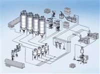
Positive Pressure Conveying System
- The positive pressure conveying system is convenient for installing branch pipelines, which can convey materials to multiple places at the same time, with high production efficiency.
- The air leakage position of the positive pressure conveying system is easy to find, and the dust removal requirement for air is not high.
- The system has small conveying resistance and less wear on the pipeline.
- The positive pressure conveying system has a long conveying distance, which can reach more than 1000m.
- Air supplement pipes can be installed inside and outside the conveying pipeline, and air supplement and blockage removal can be carried out in a variety of ways.
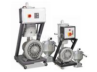
High-Power Vacuum Loader
- High-Power Vacuum Loader is a model specially developed for scenarios with large material consumption, catering to the high-volume material needs of industrial production.
- The motor power, feeding pipe diameter and hopper capacity all adopt enlarged configurations to meet the material handling requirements of large-scale industrial operations.
- Equipped with microcomputer control, it provides material shortage and overload alarms, ensuring safe and reliable operation of the material conveying system.
- It has a small size, occupies little space and features flexible operation, making it easy to integrate into different industrial production line layouts.
- Customizable one-machine multi-hopper type vacuum loaders are available to meet the diverse material conveying needs of different industrial production lines.
Electric Vacuum Feeder
- The power source of the whole set of equipment is compressed air, and no power supply is used;
- The equipment is easy and simple to disassemble and clean;
- The equipment operates with very low noise and does not generate heat or oil pollution;
- The powder conveying process is carried out in a closed environment, without dust leakage.
Vacuum Feeder
- Simple and automatic control, with arbitrary setting of suction time, easy and convenient operation.
- Hygienic closed conveying, no dust leakage, no cross-contamination, in line with GMP standards, and sterile equipment can be provided.
- It occupies a small space, can complete the conveying of powders in narrow spaces, makes the working space neat and elegant, and is not limited by the length of the distance.
- Clean and dust-free operation, no dead ends, and quick and convenient disassembly, assembly, cleaning, and material change.
- Economical: One machine can be used for multiple sets of equipment in turn, with high efficiency and energy saving, no need for warm-up and standby, and low operation and maintenance costs.
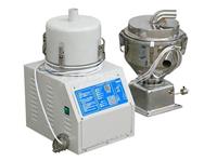
Split-Type Vacuum Loader
- The split-type vacuum loader is equipped with a stainless steel hopper, which ensures that raw materials are not contaminated during the conveying process.
- It adopts microcomputer control, featuring easy operation and precise control. Additionally, it is equipped with multiple alarm indicator lights to promptly remind operators of equipment status.
- The motor protection device of the split-type vacuum loader can extend its service life. The material shortage alarm can proactively notify customers to resolve the issue in a timely manner.
- It is equipped with an independent filter device for easy removal of accumulated dust; the filter inspection window allows customers to check the usage status of the filter and perform regular cleaning, ensuring the equipment's stable operation.
- The vacuum hopper (YMH) of the split-type vacuum loader can be directly installed on the hopper of the molding machine; the electric eye hopper (YVH) can be directly installed at the feed inlet of the molding machine, facilitating integration with production lines.
- A cyclone dust collector can be optionally configured for the split-type vacuum loader, which reduces the frequency of filter cleaning and is suitable for crushed material conveying.
- The YPV-U European-style two-material proportional valve (including an optional control box) can be optionally configured for the split-type vacuum loader, which is used for mixed use of new materials and crushed materials or immediate recycling of crushed materials.
- When crushed materials account for more than 30% of the conveyed raw materials, it is recommended to select a 14-mesh stainless steel filter screen for the split-type vacuum loader to ensure smooth conveying.